Embedded Development Board Learning
Visual Studio Code for ARM with CMake #2 Project
Date: enero 9, 2023
Author: Guillermo Garcia
Categories: Visual Studio Code Tags: Development tools
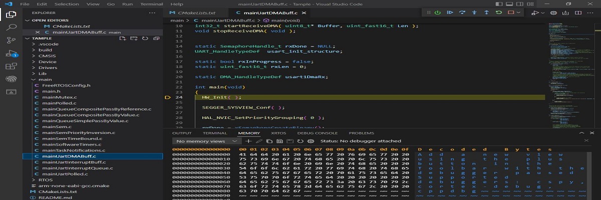
We have installed the necessary tools in the first article of the series, Visual Studio Code for ARM with CMake #1 Installation. In this article, we will create a project structure that we will use throughout this series.
We will be working on a NUCLEO-G071RB development kit. Remember that this environment can be configured for any platform based on the ARM architecture.
Table of Contents
Defining a Project Structure
We will start by defining a project structure to organize the source files where our main application and controllers will be located.
We go to Visual Studio Code and create a series of folders to organize our source files.
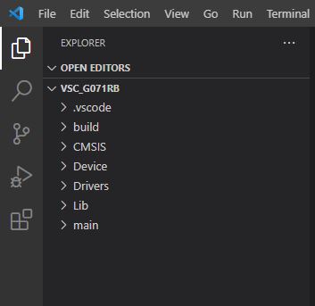
Here is a description of what type of file each folder will contain.
Folders
However this project structure works for me, but it’s really up to you how you organize the files.
SDK for NUCLEO-G071RB kit
It’s time to collect the drivers for our MCU. For this series, we have chosen a very basic MCU because we want to keep it simple.
For the STM32 platform, it provides the HAL drivers, so we will use these drivers. To do this, we download the STM32G0 library from the ST website.
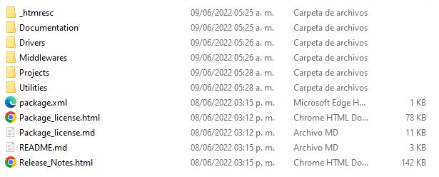
Here we have all the source files we need. Let’s start placing the files in the corresponding folders.
CMSIS
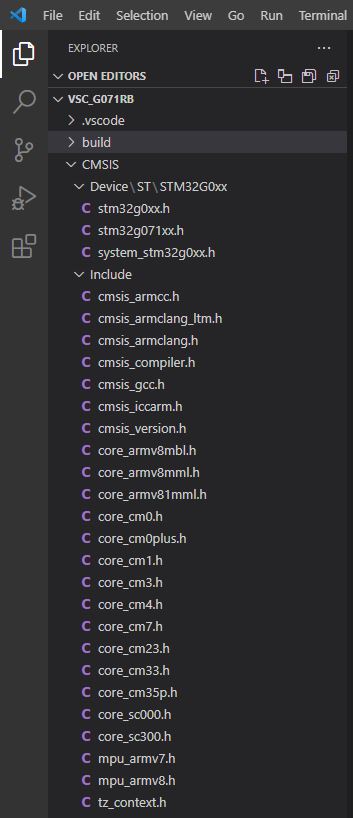
Inside the STM32G0 library, we find the necessary files for CMSIS. We add the corresponding header files for our G071RB.
Device
Here, we need to search within the STM32G0 library to find the specific files for our G071RB.
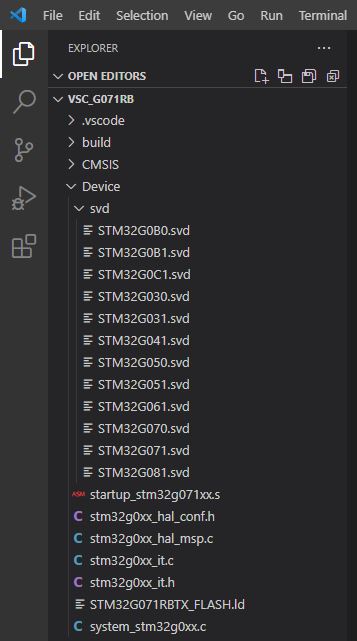
Inside the Device folder, we add the SVD files. These files contain a description of the MCU hardware at the peripheral level. They are important because our debugging tool needs this description to map the registers during debugging.
These files can be downloaded from the ST-svd page.
Drivers
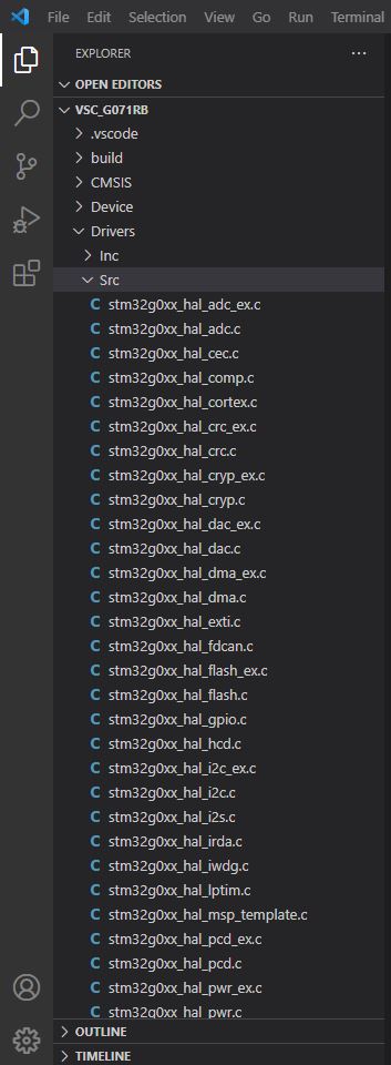
We look for the STM32G0 drivers folder and place them inside this folder. In the compilation settings we will choose which drivers to add to the compilation process.
Lib
For now we will not put anything in this folder, later in future articles we will add support for SEGGER RTT and SystemView.
main
We will create our main input source file and main function.

main.c
#include "main.h"

void SystemClock_Config(void);
static GPIO_InitTypeDef  GPIO_InitStruct = {0};

int main(void)
{

  HAL_Init();

  SystemClock_Config();

  __HAL_RCC_GPIOA_CLK_ENABLE();

  GPIO_InitStruct.Mode  = GPIO_MODE_OUTPUT_PP;
  GPIO_InitStruct.Pull  = GPIO_PULLUP;
  GPIO_InitStruct.Speed = GPIO_SPEED_FREQ_HIGH;

  GPIO_InitStruct.Pin = GPIO_PIN_5;
  HAL_GPIO_Init(GPIOA, &GPIO_InitStruct);

  while(1)
  {
    HAL_GPIO_TogglePin(GPIOA, GPIO_PIN_5);

    HAL_Delay(100);
  }

  return 0;
}

void SystemClock_Config(void)
{
  RCC_OscInitTypeDef RCC_OscInitStruct = {0};
  RCC_ClkInitTypeDef RCC_ClkInitStruct = {0};

  /** Configure the main internal regulator output voltage
  */
  HAL_PWREx_ControlVoltageScaling(PWR_REGULATOR_VOLTAGE_SCALE1);

  /** Initializes the RCC Oscillators according to the specified parameters
  * in the RCC_OscInitTypeDef structure.
  */
  RCC_OscInitStruct.OscillatorType = RCC_OSCILLATORTYPE_HSI;
  RCC_OscInitStruct.HSIState = RCC_HSI_ON;
  RCC_OscInitStruct.HSIDiv = RCC_HSI_DIV1;
  RCC_OscInitStruct.HSICalibrationValue = RCC_HSICALIBRATION_DEFAULT;
  RCC_OscInitStruct.PLL.PLLState = RCC_PLL_ON;
  RCC_OscInitStruct.PLL.PLLSource = RCC_PLLSOURCE_HSI;
  RCC_OscInitStruct.PLL.PLLM = RCC_PLLM_DIV4;
  RCC_OscInitStruct.PLL.PLLN = 70;
  RCC_OscInitStruct.PLL.PLLP = RCC_PLLP_DIV10;
  RCC_OscInitStruct.PLL.PLLQ = RCC_PLLQ_DIV5;
  RCC_OscInitStruct.PLL.PLLR = RCC_PLLR_DIV5;
  if (HAL_RCC_OscConfig(&RCC_OscInitStruct) != HAL_OK)
  {

  }

  /** Initializes the CPU, AHB and APB buses clocks
  */
  RCC_ClkInitStruct.ClockType = RCC_CLOCKTYPE_HCLK|RCC_CLOCKTYPE_SYSCLK
                              |RCC_CLOCKTYPE_PCLK1;
  RCC_ClkInitStruct.SYSCLKSource = RCC_SYSCLKSOURCE_PLLCLK;
  RCC_ClkInitStruct.AHBCLKDivider = RCC_SYSCLK_DIV1;
  RCC_ClkInitStruct.APB1CLKDivider = RCC_HCLK_DIV1;

  if (HAL_RCC_ClockConfig(&RCC_ClkInitStruct, FLASH_LATENCY_2) != HAL_OK)
  {

  }
}
main.h
#ifndef _MAIN_PROGRAM_
#define _MAIN_PROGRAM_

#ifdef __cplusplus
 extern "C" {
#endif

#include "stm32g0xx_hal.h"
#include "stm32g071xx.h"
#include "stm32g0xx.h"

#ifdef __cplusplus
 }
#endif
#endif /* _MAIN_PROGRAM_ */

Deja una respuesta