Embedded Development Board Learning
ESP32 DEVKITC V4
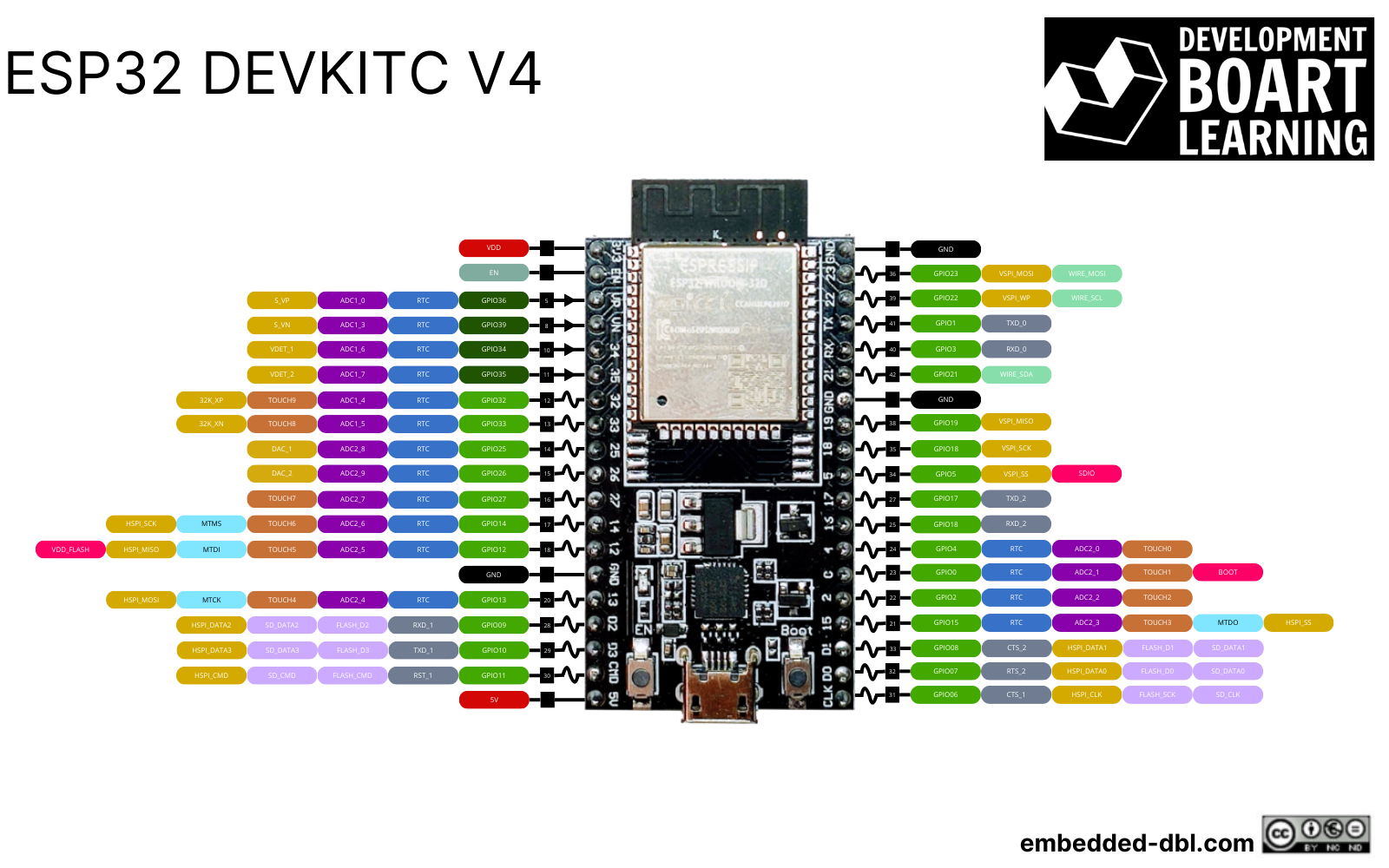
| MCU | ESP32-D0WDQ6 |
|---|---|
| Family | ESP32-WROOM-32 |
| Vendor | Espressif |
| RAM | 4 MB of PSRAM |
| Flash | default 4 MB custom flash sizes of 8 MB and 16 MB |
| Frequency | 80 MHz to 240 MHz |
| Timers | 8 hardware timers |
| UARTs | 3 UART interfaces |
| I2Cs | 2 I2C interfaces |
| SPIs | 4 SPI interfaces |
| CANs | 1 CAN controller |
| Datasheet | Datasheet |
| Reference Manual | Reference Manual |
| Board Manual | Board Manual |